Creating a 3D model of a fan blade is a fundamental skill in computer-aided design (CAD), especially for industries like aerospace and manufacturing. CATIA, a powerful 3D design software, offers a robust set of tools to achieve this. This guide will walk you through the process of making a fan blade model in CATIA, from sketching the profile to generating the solid model.
Sketching the Fan Blade Profile
The first step is to create the 2D profile of your fan blade. This will serve as the foundation for the 3D model.
- Open a new CATIA Part Design workbench. This is where you’ll create the 3D model.
- Select a plane (like xy, yz, or zx) to start your sketch. The choice depends on how you want to orient your blade initially.
- Use the Profile tool to begin sketching the outline of your fan blade. You’ll be using lines, arcs, and splines to accurately represent the blade’s shape.
- Start with the leading edge, which is usually a curve. Utilize splines for a smooth aerodynamic shape.
- Define the trailing edge, which can be sharp or rounded depending on the fan’s design.
- Connect the leading and trailing edges with lines or curves, defining the upper and lower surfaces of the blade.
- Add features like twist and taper. Fan blades often have a twist along their length to optimize airflow. You can incorporate this by varying the profile at different sections of the blade. Taper, a gradual reduction in width, can be added similarly.
- Use construction lines for symmetry and guidance. They help in maintaining symmetry and ensuring your profile is accurate.
- Dimension your sketch fully. This is crucial for controlling the blade’s size and proportions.
Creating the 3D Fan Blade Model
With the 2D profile ready, you can now create the 3D model of the fan blade.
- Exit the Sketcher workbench.
- Use the Pad tool. Select the profile you created and give it an extrusion value. This will give your 2D sketch a thickness, turning it into a basic 3D shape.
- Add the twist. You’ll use the Multi-sections Solid tool. This tool lets you modify the shape of the blade along its length, allowing for the twist.
- Refine the blade shape. Use tools like Fillet to round off sharp edges, and Shell to hollow out the blade if needed. These operations will make your model more realistic and functional.
Assembling the Fan (Optional)
If you need to create a complete fan assembly, you can follow these steps:
- Create a new CATIA Assembly Design workbench.
- Insert multiple instances of your fan blade model. You can arrange them in a circular pattern to form the fan.
- Add a hub. This is the central part of the fan to which the blades are attached. You can create this separately and insert it into the assembly.
- Constrain the components. Use assembly constraints to connect the blades to the hub and ensure they’re positioned correctly.
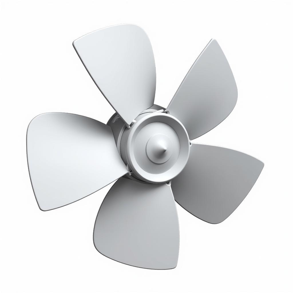 Complete Fan Assembly
Conclusion
Creating a fan blade model in CATIA is a multi-step process that combines 2D sketching, 3D modeling, and assembly techniques. By following the steps outlined in this guide, you can efficiently design and model accurate and realistic fan blades tailored to your specific requirements. Mastering these tools and techniques will equip you with the skills needed for more complex CAD projects in various engineering fields.