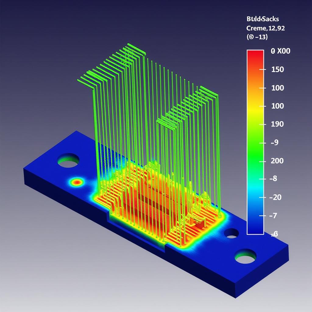
Fan boundary conditions are crucial for accurately simulating airflow and thermal performance in SOLIDWORKS Flow Simulation 2019. Whether you’re designing a cooling system for electronics or analyzing airflow in a building, understanding how to effectively use fan boundary conditions can significantly impact the accuracy and reliability of your simulation results.
Types of Fan Boundary Conditions
SOLIDWORKS Flow Simulation 2019 offers several types of fan boundary conditions, each with its unique characteristics and applications:
-
Internal Fan: This type of fan is typically used to represent axial fans located within the computational domain. You define the fan’s location, diameter, rotational speed, and flow direction. Internal fans are ideal for simulating components like CPU fans or ventilation fans within an enclosure.
-
External Fan: External fans simulate fans located outside the computational domain but influence the flow within it. These are often used to represent exhaust fans or blowers that draw or push air from/to the system.
-
Swept Fan: Ideal for cases where the fan geometry is complex and cannot be easily represented as a simple disc, the swept fan boundary condition takes a 2D sketch of the fan blade profile and sweeps it along a path to create the 3D fan geometry.
Defining Fan Performance Parameters
To ensure accurate simulation results, you need to define the fan’s performance characteristics accurately. SOLIDWORKS Flow Simulation allows you to specify these parameters in several ways:
-
Fan Curve: The most accurate method involves using a fan curve provided by the manufacturer. This curve plots the relationship between the fan’s flow rate and pressure rise (or pressure drop).
-
Flow Rate and Pressure Rise: You can directly input the fan’s flow rate and the corresponding pressure rise. This method is less accurate than a fan curve but can be suitable for initial design iterations or when a fan curve is unavailable.
-
Rotational Speed and Pressure Rise: This method is typically used for internal fans. You specify the fan’s rotational speed and the pressure rise it generates.
Common Applications and Examples
Let’s explore some practical examples of how fan boundary conditions are used in SOLIDWORKS Flow Simulation 2019:
Electronics Cooling: Designing effective cooling systems for electronic components is paramount to prevent overheating. Fan boundary conditions can simulate the airflow generated by cooling fans, helping engineers optimize heat sink designs, fan placement, and airflow paths within enclosures.
HVAC System Design: Engineers use fan boundary conditions to model the behavior of HVAC systems in buildings. By simulating the airflow generated by fans and blowers, they can evaluate system efficiency, optimize ductwork design, and ensure proper air distribution within a room or building.
Automotive Applications: From engine cooling to cabin climate control, fan boundary conditions play a crucial role in automotive design. By accurately simulating airflow patterns, engineers can optimize component placement, improve thermal management, and reduce aerodynamic drag.
 Fan Simulation Results
Tips for Effective Fan Boundary Condition Setup
Here are some valuable tips to enhance the accuracy and effectiveness of your fan boundary conditions in SOLIDWORKS Flow Simulation 2019:
-
Mesh Refinement: Ensure that the mesh around the fan region is sufficiently refined to capture the flow details accurately.
-
Turbulence Model Selection: Choose an appropriate turbulence model that aligns with the flow characteristics around the fan.
-
Boundary Condition Placement: Carefully consider the placement of fan boundary conditions relative to other components in your model. Improper placement can lead to inaccurate results.
-
Validation with Experimental Data: Whenever possible, validate your simulation results against experimental data to ensure the accuracy of your setup.
Conclusion
Mastering fan boundary conditions in SOLIDWORKS Flow Simulation 2019 is essential for engineers and designers working on projects involving fluid flow and thermal management. By understanding the different types of fan boundary conditions, accurately defining fan performance parameters, and following best practices for setup, you can leverage the power of simulation to optimize designs, improve product performance, and reduce development costs.
If you need help with SOLIDWORKS Flow Simulation, please contact us at Phone Number: 0903426737, Email: fansbongda@gmail.com, or visit us at Lot 9, Area 6, Gieng Day Ward, Ha Long City, Gieng Day, Ha Long, Quang Ninh, Vietnam. We have a 24/7 customer support team.


