Solidworks Flow Simulation is a powerful tool for analyzing fluid flow and heat transfer, and understanding how to effectively utilize fans within this environment is crucial for accurate and insightful simulations. Whether you’re designing a cooling system for electronics, analyzing airflow in a building, or optimizing the performance of a fan itself, mastering fan setup in Solidworks Flow Simulation is a key skill. This article will guide you through the process, offering tips, tricks, and best practices to ensure your simulations yield reliable results.
Defining Your Fan in Solidworks Flow Simulation
Before diving into the simulation, it’s essential to properly define your fan within the Solidworks model. This involves accurately representing the fan’s geometry, specifying its operational characteristics, and ensuring its integration within the overall assembly. Consider factors like blade shape, hub diameter, and housing design, as these will influence the airflow characteristics.
Specifying Fan Performance Data
Solidworks Flow Simulation offers various methods for defining fan performance. You can input performance curves obtained from manufacturers or experimental data, specifying parameters like pressure rise, flow rate, and efficiency. Alternatively, you can use the built-in fan curve library or create your own customized fan curves. Selecting the right approach depends on the level of detail required and the available data.
Boundary Conditions and Meshing for Fan Simulations
Setting appropriate boundary conditions is critical for accurate fan simulations. Defining the inlet and outlet conditions, including pressure, temperature, and flow direction, is essential for creating a realistic representation of the flow environment. Additionally, proper meshing around the fan is crucial for capturing the complex flow patterns.
How to Design Fan Blade for Optimal Performance
Designing fan blades plays a significant role in the overall performance of the fan within the simulation. Factors such as blade angle, chord length, and number of blades impact the pressure rise, flow rate, and efficiency. Solidworks provides tools for optimizing blade design, allowing you to iterate and refine your design for optimal performance. how to design fan blade
Analyzing Fan Simulation Results
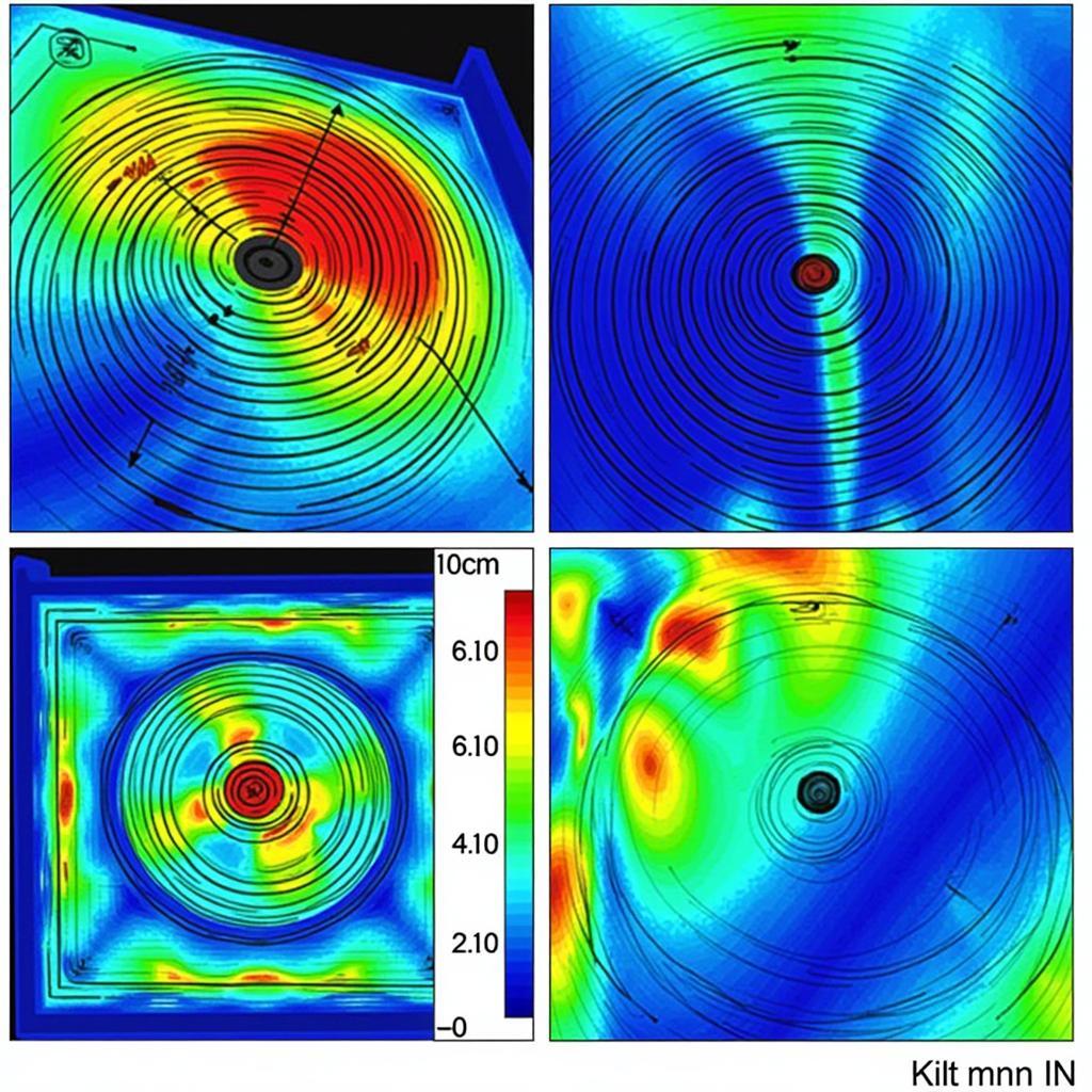
Once the simulation is complete, Solidworks Flow Simulation provides a range of tools for analyzing the results. You can visualize flow patterns, pressure distributions, and temperature gradients to understand the fan’s impact on the overall system. Furthermore, you can extract performance data, such as flow rate and pressure rise, to validate your design and make informed decisions.
Troubleshooting Common Fan Simulation Issues
Occasionally, fan simulations may encounter issues such as convergence problems or unrealistic results. Understanding common pitfalls and troubleshooting techniques can help you resolve these issues and ensure accurate simulations. Consider factors such as mesh quality, boundary condition setup, and fan performance data accuracy. fan in solidworks flow simulation 2019
“Accurate representation of fan performance data is paramount for achieving reliable simulation results,” says Dr. David Miller, a leading expert in CFD analysis. “Always ensure the data you input aligns with the specific fan being modeled.”
Conclusion
Mastering Fan In Solidworks Flow Simulation is essential for accurately analyzing and optimizing fluid flow systems. By carefully defining fan geometry, specifying performance data, setting appropriate boundary conditions, and analyzing the simulation results, you can gain valuable insights and make informed design decisions. Understanding these principles and applying best practices will empower you to leverage the full potential of Solidworks Flow Simulation for your fan-related projects. blower fan 3d model Remember to thoroughly validate your results and iterate on your design until you achieve the desired performance.
 Analyzing Fan Simulation Results
“The key to successful fan simulations lies in the combination of accurate geometry representation, precise boundary condition setup, and reliable performance data,” adds Dr. Emily Carter, a renowned CFD consultant. “Don’t underestimate the importance of proper meshing, especially around the fan blades, for capturing the intricate flow details.”
FAQ
- How do I import fan performance data into Solidworks Flow Simulation?
- What are the different types of fan boundary conditions available?
- How can I improve the accuracy of my fan simulations?
- What are common issues encountered in fan simulations and how can I troubleshoot them?
- How can I optimize fan blade design using Solidworks Flow Simulation?
- What are the best practices for meshing around a fan in Solidworks Flow Simulation?
- How can I visualize and interpret the results of a fan simulation?
What are other common issues encountered in fan simulation in Solidworks?
For more information, you can also check out: fan 120 x 120 grabcad
Need help with your Solidworks Flow Simulation projects? Contact us at Phone Number: 0903426737, Email: fansbongda@gmail.com or visit our address: To 9, Khu 6, Phuong Gieng Day, Thanh Pho Ha Long, Gieng Day, Ha Long, Quang Ninh, Vietnam. We have a 24/7 customer support team ready to assist you.


