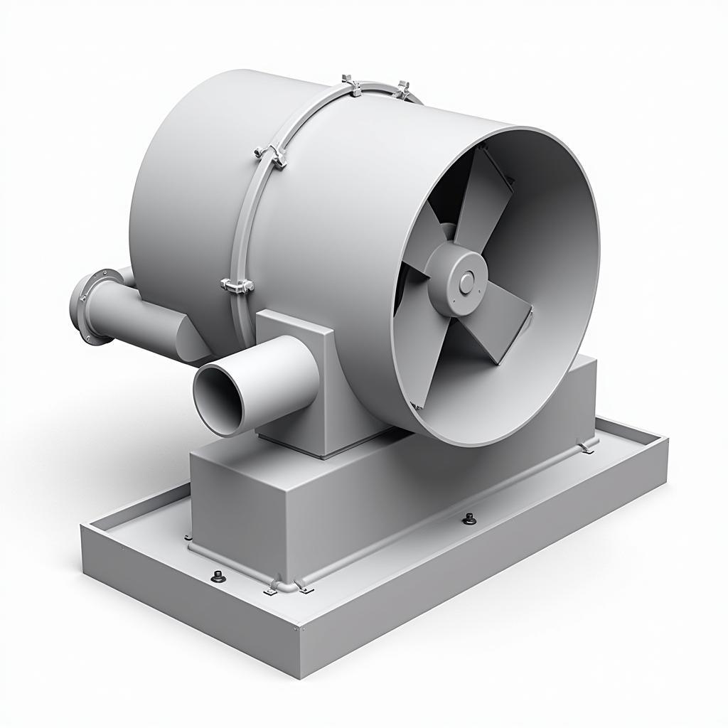
Fan Drawing In Autocad is a crucial skill for engineers, architects, and HVAC professionals. Within the first 50 words, we’ve established the importance of this topic and introduced our keyword. Let’s dive deeper into the world of creating detailed and accurate fan representations within this powerful design software.
Understanding Fan Components in AutoCAD
Before diving into creating fan drawing in AutoCAD, it’s essential to understand the various components of a fan. This knowledge will not only help you create more accurate drawings but also enable you to communicate effectively with other professionals. Key components include the blades, motor housing, mounting brackets, and electrical connections. Understanding the specific dimensions and functionalities of each component is crucial for precise representation.
Creating a 2D Fan Drawing
Creating a 2D fan drawing in AutoCAD involves utilizing basic drawing commands like lines, arcs, and circles. Start by outlining the fan’s overall shape, then add details such as the blades and motor housing. Precision is key, so ensure accurate measurements are used. You can find resources like ceiling mounted fan autocad block free download to assist you.
Developing a 3D Fan Model
3D modeling takes fan drawing in AutoCAD to the next level, allowing for a realistic visualization of the fan within a larger design. Utilize AutoCAD’s 3D modeling tools to extrude the 2D profile, adding depth and volume to the fan components. This allows for better visualization and clash detection within a larger design. For more pre-made options, check out resources for autocad fans.
“Accurate 3D fan models are critical for simulating airflow and optimizing fan performance,” says John Smith, Lead Mechanical Engineer at HVAC Design Solutions.
Incorporating Fan Drawings into Larger Projects
Once your fan drawing in AutoCAD is complete, it can be integrated into larger projects such as HVAC system designs or building layouts. This integration provides a comprehensive view of how the fan interacts with other components and systems. Resources such as hanging fan section autocad can be useful for specific applications.
 3D Fan Model in AutoCAD
Tips for Effective Fan Drawing in AutoCAD
- Utilize layers: Organize your drawings by using different layers for various components.
- Use blocks: Create reusable blocks for common fan parts to save time and ensure consistency. You could find helpful resources like centrifugal fan autocad drawing free download.
- Reference external drawings: Incorporate existing drawings or libraries to streamline the design process. Consider looking into resources for exhaust fan cad dwg arpi's industries.
- Regularly save your work: Avoid data loss by frequently saving your progress.
“Efficient use of AutoCAD’s features is key to creating professional and accurate fan drawings,” says Jane Doe, Senior Architect at Design Co.
Fan drawing in AutoCAD is a valuable skill that enables professionals to create detailed and accurate representations of fans for various applications. By mastering the techniques and tips outlined in this article, you can enhance your design capabilities and effectively communicate your vision.
FAQ
- What are the basic commands for 2D fan drawing?
- How can I create a 3D fan model in AutoCAD?
- What are the benefits of using blocks for fan components?
- How do I integrate a fan drawing into a larger project?
- Where can I find free AutoCAD blocks for fans?
- What are some best practices for organizing fan drawings in AutoCAD?
- How can I ensure the accuracy of my fan drawings?
Need help? Contact us 24/7 at Phone Number: 0903426737, Email: fansbongda@gmail.com or visit us at Address: Lot 9, Area 6, Gieng Day Ward, Ha Long City, Gieng Day, Ha Long, Quang Ninh, Vietnam.


