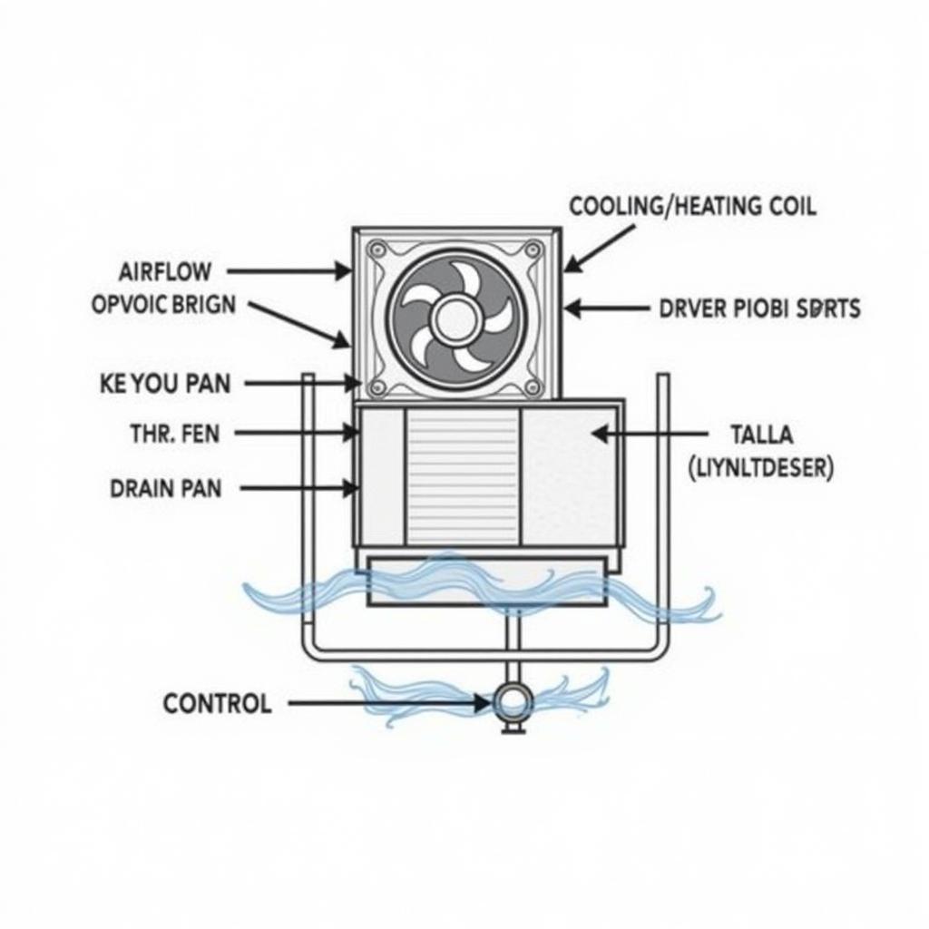
A Fan Coil Unit Diagram is essential for understanding the inner workings of these HVAC systems. It provides a visual representation of the components and their connections, facilitating installation, maintenance, and troubleshooting. This article delves into the various aspects of fan coil unit diagrams, from basic components to more complex system integrations. fan coil unit schematic diagram
Decoding the Basics of a Fan Coil Unit Diagram
A typical fan coil unit diagram illustrates the key components, including the fan, coil (heating or cooling), filter, drain pan, and control system. Understanding these elements and their interconnections is crucial for effective operation and maintenance.
 Basic Fan Coil Unit Diagram Components and Connections
The diagram also shows the flow of air and water (or refrigerant) through the unit. The air is drawn in through the filter, passes over the coil where it is heated or cooled, and then is distributed into the room. The water (or refrigerant) circulates through the coil, providing the heating or cooling medium.
Different Types of Fan Coil Unit Diagrams
Various types of fan coil unit diagrams cater to different purposes. A simplified diagram might only show the main components and connections, while a more detailed diagram might include wiring diagrams, control system schematics, and piping layouts. catalogue fan coil unit analog diagram provides further details on this.
Schematic Diagrams
Schematic diagrams focus on the electrical connections and control circuits within the fan coil unit. These diagrams are essential for troubleshooting electrical issues and understanding the control logic.
Piping and Instrumentation Diagrams (P&IDs)
P&IDs illustrate the piping connections, valves, and instrumentation associated with the fan coil unit. They provide a comprehensive view of the system’s hydraulics and are crucial for installation and maintenance.
Integrating Fan Coil Units into Larger Systems
Fan coil units are often integrated into larger HVAC systems, such as those using chillers or boilers. Understanding the connection diagrams between these components is crucial for proper system operation. between fcu fan coil unit and water chiller connection diagram offers a detailed explanation of this integration.
Connecting to Chillers
When connected to a chiller, the fan coil unit diagram will show the chilled water supply and return lines, along with any control valves and other components.
Connecting to Boilers
Similarly, when connected to a boiler, the diagram will show the hot water supply and return lines. Understanding these connections is critical for balancing the system and ensuring efficient heating and cooling.
Troubleshooting with Fan Coil Unit Diagrams
Diagrams are invaluable troubleshooting tools. By tracing the flow of air and water (or refrigerant) through the diagram, technicians can identify potential problems and develop solutions. dx fan coil provides additional information on specialized fan coil systems.
 Troubleshooting a Fan Coil Unit Using a Diagram
Conclusion
A fan coil unit diagram is an indispensable resource for anyone working with these HVAC systems. From installation and maintenance to troubleshooting and system design, understanding the information presented in these diagrams is essential for optimal performance and efficiency. fan coil cooling capacity calculation can help you determine the appropriate size and capacity for your specific needs.
FAQ
- What are the main components of a fan coil unit?
- What are the different types of fan coil unit diagrams?
- How are fan coil units connected to chillers and boilers?
- How can diagrams be used for troubleshooting?
- Where can I find more information on fan coil unit diagrams?
- What is the purpose of a drain pan in a fan coil unit?
- How does the control system regulate the fan coil unit’s operation?
Need help? Contact us at Phone Number: 0903426737, Email: fansbongda@gmail.com Or visit us at: To 9, Khu 6, Phuong Gieng Day, Thanh Pho Ha Long, Gieng Day, Ha Long, Quang Ninh, Vietnam. We have a 24/7 customer service team.


