Exhaust fan thermostats offer a convenient way to control ventilation based on temperature, ensuring optimal comfort and energy efficiency. This article will delve into the intricacies of Exhaust Fan Thermostat Wiring Diagrams, empowering you to understand, install, and troubleshoot these systems effectively.
Decoding the Exhaust Fan Thermostat Wiring Diagram
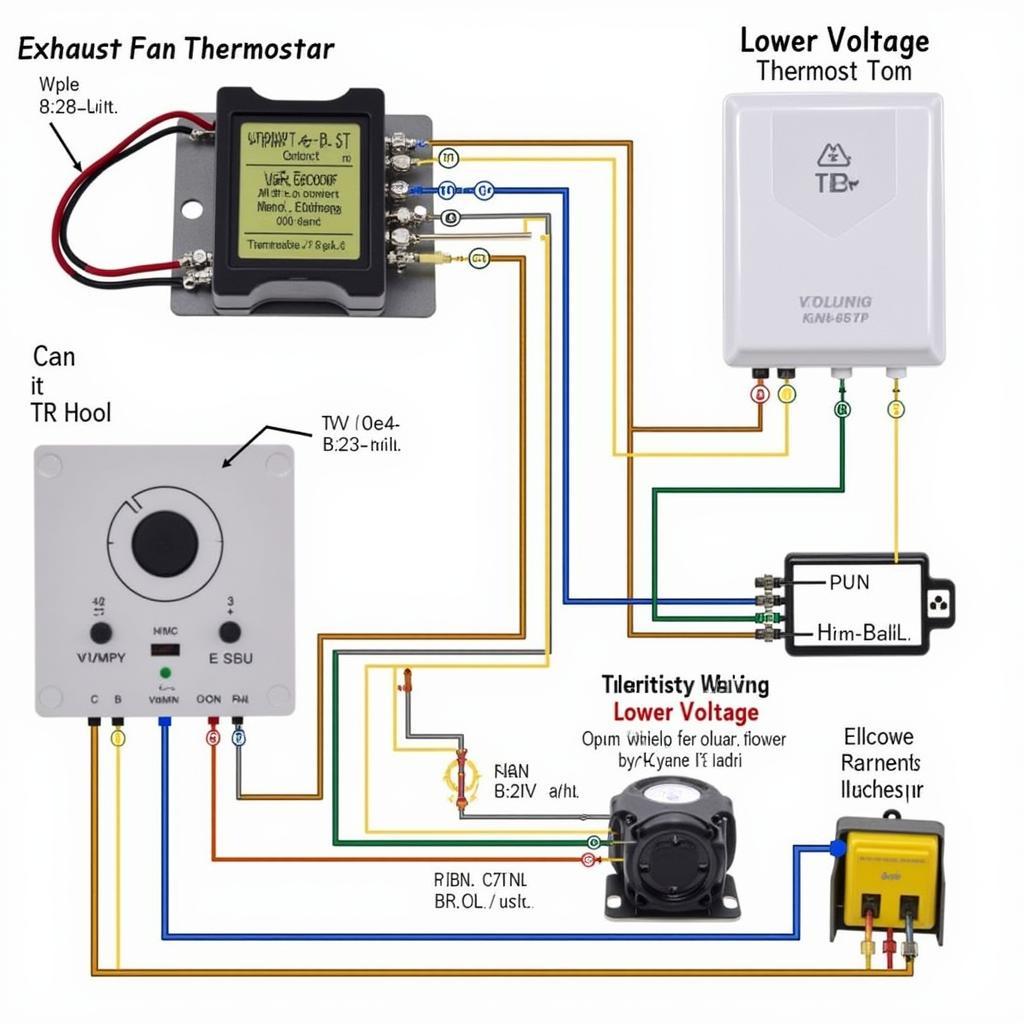
An exhaust fan thermostat wiring diagram is essentially a roadmap that guides you through the connections between the thermostat, the exhaust fan, and the power supply. Understanding this diagram is crucial for proper installation and operation. The diagram typically depicts the various terminals on the thermostat and their corresponding connections to the fan and power source.
Different thermostats have different terminal configurations, so it’s essential to consult the specific wiring diagram for your particular model. However, some common terminals include “L1” and “L2” for the power supply, “T1” and “T2” for the thermostat connection to the fan motor, and “G” for the fan.
Common Types of Exhaust Fan Thermostats
There are several types of exhaust fan thermostats available, each designed for specific applications. Choosing the right type depends on factors such as the type of fan, the location of the thermostat, and the desired control features.
Line Voltage Thermostats
These thermostats are directly connected to the power supply and can handle the full voltage of the fan motor. They are commonly used for larger exhaust fans in industrial or commercial settings.
Low Voltage Thermostats
Low voltage thermostats operate on a lower voltage and require a transformer to step down the voltage from the main power supply. They are often used in residential applications and offer greater safety and flexibility.
 Low Voltage Exhaust Fan Thermostat Wiring Diagram
Smart Thermostats
Smart thermostats offer advanced features such as programmable schedules, remote control, and integration with other smart home devices. They can provide significant energy savings and improved control over ventilation.
Troubleshooting Common Wiring Issues
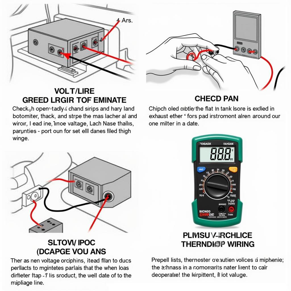
Occasionally, you may encounter problems with your exhaust fan thermostat. Understanding common wiring issues can help you diagnose and fix these problems quickly.
- Fan Not Turning On: This could be due to a loose wire connection, a faulty thermostat, or a tripped breaker. Check the wiring diagram and ensure all connections are secure.
- Fan Runs Continuously: This may indicate a problem with the thermostat itself. Try replacing the thermostat to see if that resolves the issue.
- Inaccurate Temperature Readings: This could be caused by a faulty thermostat sensor or incorrect placement of the thermostat. Ensure the thermostat is installed in a location that accurately reflects the room temperature.
 Troubleshooting Exhaust Fan Thermostat Wiring
Conclusion
Understanding exhaust fan thermostat wiring diagrams is essential for ensuring proper installation and operation of your ventilation system. By following the guidelines and troubleshooting tips outlined in this article, you can effectively control your exhaust fan based on temperature, maximizing comfort and energy efficiency. Remember to always consult the specific wiring diagram for your thermostat model and seek professional assistance if needed.
FAQ
- What type of wire should I use for connecting the thermostat to the fan?
- Can I use a regular thermostat for an exhaust fan?
- How do I test the thermostat to see if it’s working correctly?
- What safety precautions should I take when working with electrical wiring?
- Where should I install the thermostat for optimal temperature control?
- How often should I replace my exhaust fan thermostat?
- What are the benefits of using a smart thermostat for an exhaust fan?
Contact us for support: Phone: 0903426737, Email: [email protected] Or visit us at: Group 9, Area 6, Gieng Day Ward, Ha Long City, Gieng Day, Ha Long, Quang Ninh, Vietnam. We have a 24/7 customer service team.


