Exhaust Fan Dwg Files are essential resources for architects, engineers, and HVAC professionals. These files provide detailed 2D or 3D drawings of exhaust fans, allowing for precise integration into building plans and ventilation systems. Understanding how to access, utilize, and incorporate these files is crucial for efficient design and construction processes.
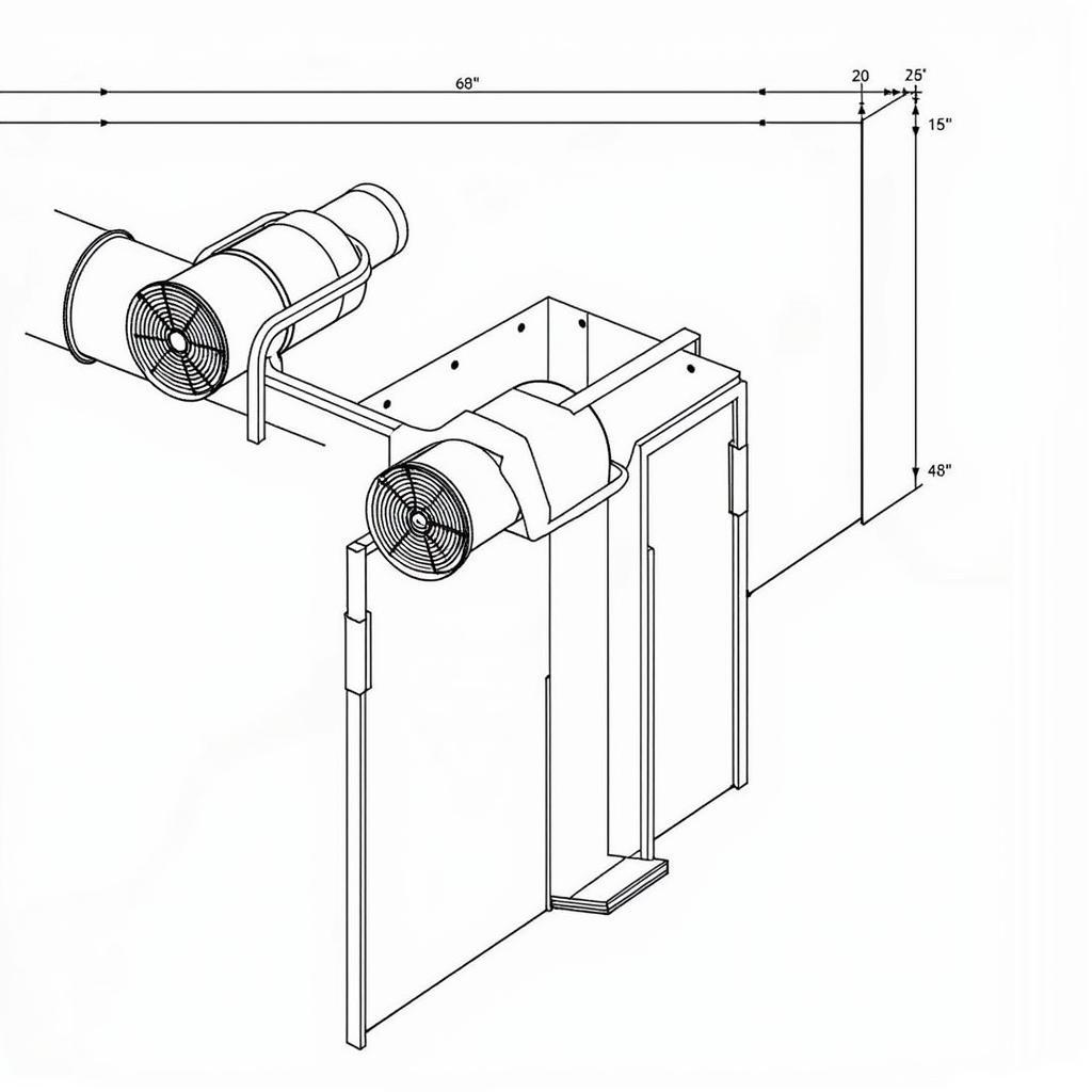
 Example of an Exhaust Fan DWG File
Understanding the Importance of Exhaust Fan DWG Files
DWG files, the native format for AutoCAD, are widely used for sharing technical drawings. They offer a standardized format for representing complex designs, ensuring compatibility across different software platforms. For exhaust fans, these files provide critical dimensions, specifications, and mounting details needed for accurate installation. Using an exhaust fan dwg file allows professionals to visualize the fan within the larger context of the building’s ventilation system. fan drawing in autocad
Why DWG Files are Crucial for HVAC Design
DWG files facilitate accurate space planning, ensuring that the exhaust fan fits seamlessly within the allocated area. This also helps in avoiding clashes with other building elements like pipes and ducts. Accurate representation of the exhaust fan in the DWG file enables precise calculations of airflow and pressure drop, ensuring optimal ventilation performance. centrifugal fan block cad
 Integrating Exhaust Fan DWG into HVAC System Design
Sourcing and Using Exhaust Fan DWG Files
Numerous online repositories and manufacturer websites offer exhaust fan DWG files for download. Carefully review the specifications of the DWG file, like the fan size, airflow capacity, and mounting type, to ensure it meets project requirements. exhaust fan cad dwg fan silencer
Tips for Working with Exhaust Fan DWG Files
- Compatibility: Ensure your CAD software is compatible with the DWG file version.
- Scaling: Verify the scale of the DWG file to ensure accurate representation in your drawings.
- Layers: Utilize layers effectively to organize different components of the exhaust fan drawing.
“Using DWG files allows for seamless collaboration between architects and HVAC engineers,” says John Smith, a Senior HVAC Engineer at ABC Engineering. “It ensures everyone is working with the same accurate information, minimizing errors and rework during construction.”
Optimizing Ventilation System Design with DWG Files
Exhaust fan DWG files play a crucial role in optimizing ventilation system design. fan inlet ring By accurately representing the fan’s dimensions and specifications, these files allow engineers to fine-tune the system for maximum efficiency. They can accurately simulate airflow patterns and pressure drops to identify potential issues and optimize ductwork layout.
Integrating Exhaust Fan DWG Files with BIM
Building Information Modeling (BIM) software can further enhance the use of exhaust fan DWG files. cad dwg fan silencer exhaust system Integrating these files into a BIM model creates a comprehensive digital representation of the building, enabling clash detection and coordination between different disciplines.
“Incorporating exhaust fan DWG files into BIM allows for a more holistic approach to building design,” adds Jane Doe, Lead Architect at XYZ Architects. “It facilitates better communication and coordination among all stakeholders, leading to a more efficient and successful project.”
In conclusion, utilizing exhaust fan dwg files is crucial for efficient and accurate HVAC system design. These files provide the necessary information for seamless integration of exhaust fans into building plans, ensuring optimal ventilation performance and minimizing errors during construction.
Please contact us at Phone Number: 0903426737, Email: fansbongda@gmail.com or visit our address: Lot 9, Zone 6, Gieng Day Ward, Ha Long City, Gieng Day, Ha Long, Quang Ninh, Vietnam for any assistance. We have a 24/7 customer service team.