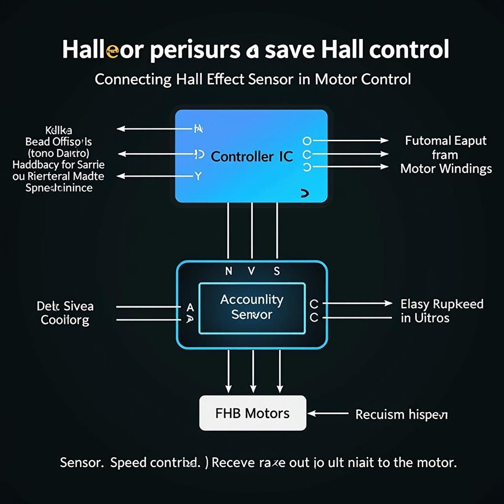
DC Brushless Direct Current (BLDC) fans are increasingly common in Daikin air conditioning systems, offering superior efficiency and control. Understanding the diagram schematics of these fans is crucial for troubleshooting, maintenance, and even installation. This guide will delve into the intricacies of “Dc Bld Fan Daikin Diagram Schematics”, providing you with a comprehensive understanding of their components, operation, and interpretation.
Decoding the DC BLD Fan Daikin Diagram
A typical Daikin DC BLD fan diagram schematic includes several key components. Recognizing these elements is the first step towards understanding the system’s function. These schematics are more than just lines and symbols; they represent the electrical flow and logic that control the fan’s operation. Understanding them allows for targeted diagnostics and efficient repairs.
Key Components in a Daikin DC BLD Fan Schematic
- Power Supply: This section depicts the input voltage and how it’s converted to the DC voltage required by the BLDC motor. It usually includes rectifiers, filters, and sometimes voltage regulators. Identifying the power supply components is crucial for diagnosing power-related issues.
- BLDC Motor: The heart of the schematic, this section represents the motor itself, showing the connections to the stator windings. The arrangement of these windings determines the motor’s rotational direction and speed.
- Hall Effect Sensors: These sensors are critical for the commutation process, providing feedback to the controller about the rotor’s position. Their placement and connection within the schematic are essential to understand how the controller regulates the motor’s speed.
- Controller IC: This integrated circuit is the brain of the operation, receiving signals from the Hall effect sensors and adjusting the power delivered to the motor windings. Understanding its inputs and outputs is crucial for analyzing control issues.
- Protection Circuitry: These circuits protect the fan from overvoltage, overcurrent, and other potential faults. Understanding their function is vital for safe operation and troubleshooting.
Interpreting the Daikin DC BLD Fan Schematic
Simply identifying the components isn’t enough; understanding their interconnections and function is vital. The schematic illustrates the flow of current and the logic that governs the fan’s operation. By tracing the connections and understanding the symbols, you can gain a deep understanding of how the system functions.
Following the Flow: A Step-by-Step Guide
- Power Input: Trace the AC input voltage through the rectifier and filter to understand how the DC voltage is generated.
- Controller Input: Examine the connections from the Hall effect sensors to the controller IC. This reveals how the controller receives information about the rotor’s position.
- Controller Output: Follow the lines from the controller IC to the motor windings. This shows how the controller energizes the coils to generate rotation.
- Protection Circuitry: Identify the overvoltage and overcurrent protection components and their connections to the power supply and motor.
 Daikin DC BLD Fan Controller IC Diagram
Troubleshooting with the Daikin DC BLD Fan Schematic
Armed with an understanding of the schematic, troubleshooting becomes a systematic process. By analyzing the symptoms and referencing the schematic, you can pinpoint the likely source of the problem. This knowledge empowers you to diagnose and resolve issues efficiently.
“Understanding the DC BLD fan schematic is like having a roadmap to the system’s inner workings,” says John Smith, a senior HVAC technician with over 20 years of experience. “It’s an invaluable tool for anyone working with these advanced fan systems.”
Common Issues and Solutions
- Fan Not Spinning: Check the power supply components for correct voltage output. Then, examine the controller IC and Hall effect sensor connections for any breaks or shorts.
- Erratic Fan Speed: Inspect the Hall effect sensors for proper alignment and function. Also, check the controller IC for any faults.
- Overheating: Verify the operation of the protection circuitry. Ensure adequate airflow and check the motor windings for shorts.
Conclusion: Mastering the DC BLD Fan Daikin Diagram Schematics
Understanding “dc bld fan daikin diagram schematics” is paramount for anyone working with these sophisticated systems. By deciphering the symbols and connections, you can unlock the secrets to efficient operation, targeted troubleshooting, and effective maintenance. This knowledge empowers you to maintain optimal performance and extend the lifespan of your Daikin air conditioning system.
FAQ
- What is a BLDC fan? A BLDC fan uses a brushless DC motor for quieter and more efficient operation.
- Why are Daikin DC BLD fan diagrams important? They are essential for understanding the fan’s operation and troubleshooting issues.
- What are Hall effect sensors? These sensors detect the rotor’s position and provide feedback to the controller.
- How can I troubleshoot a DC BLD fan using the schematic? By tracing the connections and identifying potential faults based on the symptoms.
- Where can I find more information about Daikin DC BLD fans? Refer to the Daikin website or contact their technical support.
- What is the function of the controller IC? It regulates the power delivered to the motor windings based on the feedback from the Hall effect sensors.
- Why is understanding the power supply section important? It helps diagnose power-related issues that may prevent the fan from operating.
Need help with your Daikin DC BLD fan? Contact us! Phone: 0903426737, Email: fansbongda@gmail.com Or visit us at: Lot 9, Zone 6, Gieng Day Ward, Ha Long City, Quang Ninh Province, Vietnam. We have a 24/7 customer support team.


