Catalogue Fan Coil Unit Analog Diagrams are essential tools for understanding and troubleshooting HVAC systems. These diagrams provide a visual representation of the electrical connections and control logic for fan coil units, offering valuable insights into their operation. Whether you’re an HVAC technician, building engineer, or simply curious about how these systems work, having a firm grasp of analog diagrams is crucial.
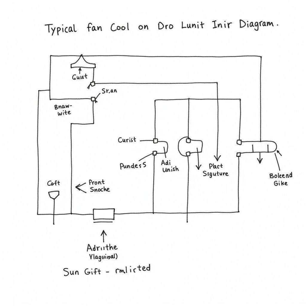 Fan Coil Unit Analog Diagram Example
Decoding the Basics of Fan Coil Unit Analog Diagrams
Analog diagrams utilize standardized symbols to represent various components within the fan coil unit, including the motor, fan, heating and cooling coils, valves, thermostats, and control relays. Lines connecting these symbols illustrate the electrical wiring and signal flow between them.
For example, a line connecting the thermostat symbol to the control relay signifies that the thermostat’s signal dictates the relay’s activation, which in turn controls the fan motor or valve operation. Understanding these symbols and connections is key to interpreting the diagram accurately.
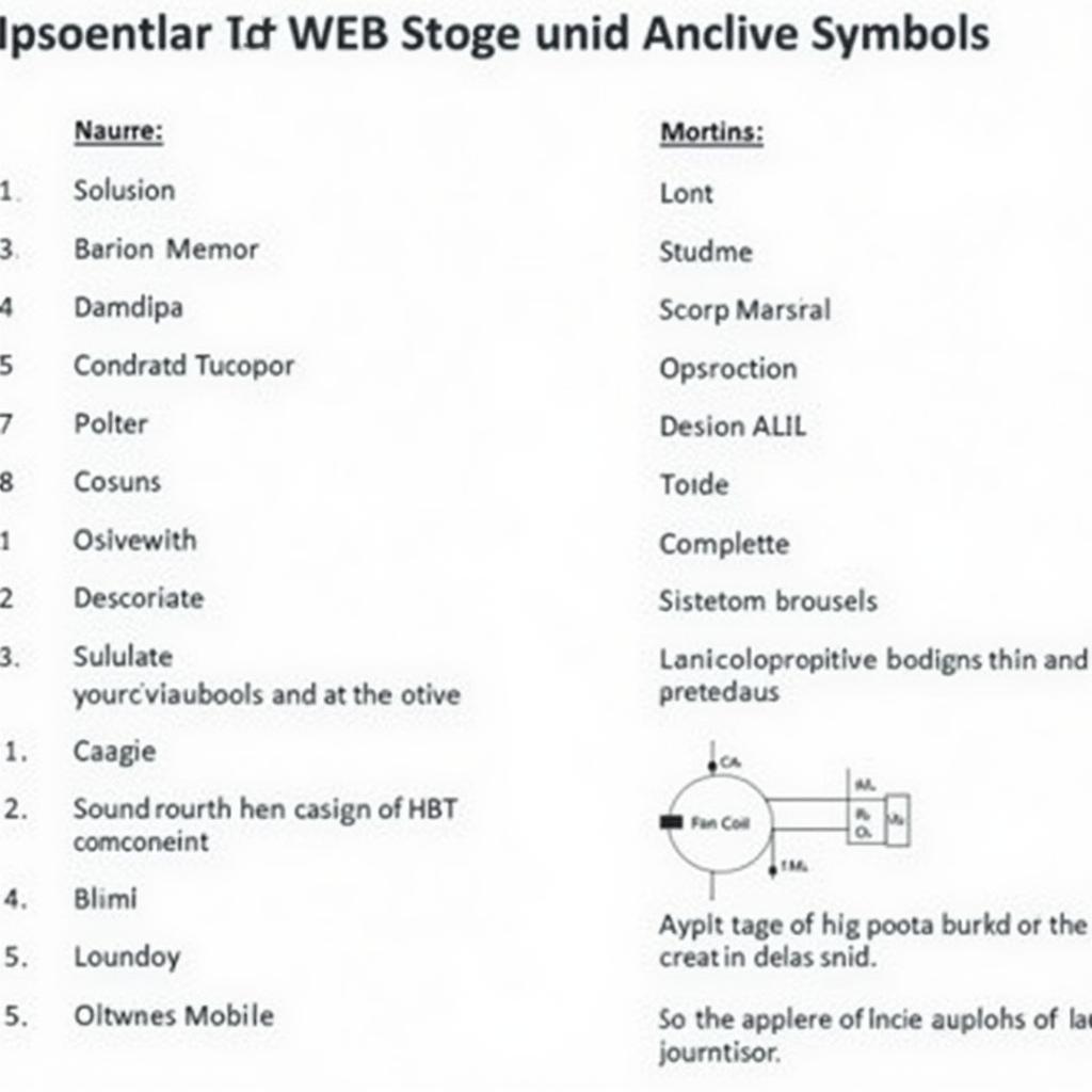 Common Fan Coil Unit Diagram Symbols
Key Components and Their Functions
Thermostat
The heart of the control system, the thermostat senses the room temperature and sends signals to maintain the desired setpoint. In an analog diagram, it’s typically depicted as a box with a temperature scale.
Control Relay
Acting as a switch, the control relay receives signals from the thermostat and energizes or de-energizes circuits to control various components, such as the fan motor or valves. It’s often represented by a rectangle with a coil and contacts.
Fan Motor
The fan motor, represented by a circle with an “M” inside, is responsible for circulating air through the unit and across the coils. The diagram illustrates its connection to the control relay and power supply.
Heating and Cooling Coils
Symbolized by a series of wavy lines, the heating and cooling coils are responsible for conditioning the air. The diagram shows their connection to the water valves and the airflow path.
Water Valves
Controlling the flow of hot or chilled water through the coils, water valves are depicted as triangles. Their connection to the control relay and the water supply lines is clearly illustrated.
Troubleshooting with Analog Diagrams
Analog diagrams are invaluable for troubleshooting fan coil unit issues. By tracing the electrical connections and understanding the control logic, technicians can identify faulty components or wiring problems.
For instance, if the fan is not running, the diagram can guide the technician to check the thermostat signal, control relay contacts, fan motor wiring, and power supply to pinpoint the source of the problem.
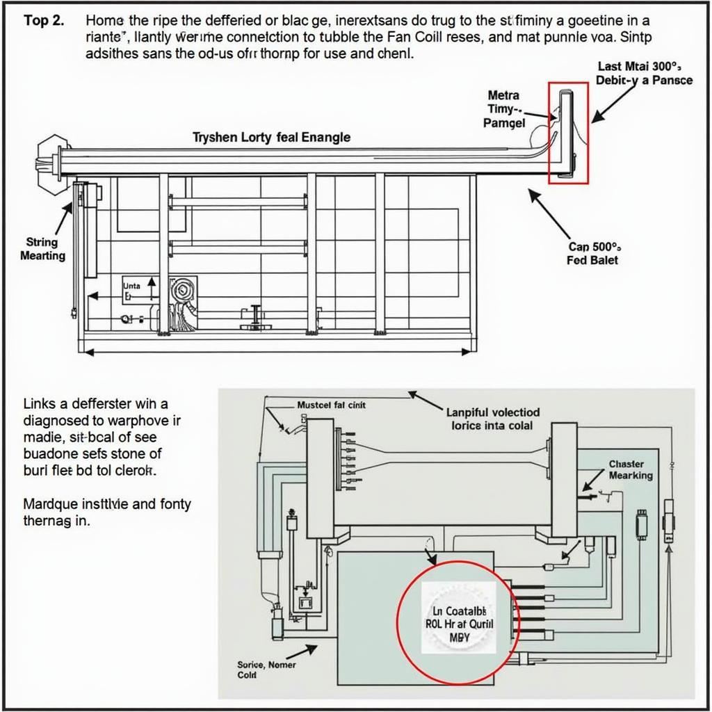 Troubleshooting Fan Coil Unit with Analog Diagram
Conclusion
Catalogue fan coil unit analog diagrams play a critical role in understanding, installing, and servicing HVAC systems. By learning the symbols, connections, and control logic, you can unlock the information these diagrams hold and ensure optimal fan coil unit performance. Familiarizing yourself with these diagrams is a worthwhile investment for anyone involved in the HVAC field.
FAQs
- What is the purpose of a fan coil unit analog diagram?
- These diagrams provide a visual representation of the electrical connections and control logic of a fan coil unit, aiding in understanding, installation, and troubleshooting.
- Where can I find the analog diagram for my specific fan coil unit?
- The analog diagram is usually found within the unit’s installation and service manual provided by the manufacturer.
- Can I modify the wiring based on the analog diagram?
- Modifications should only be performed by qualified technicians who understand the potential risks and adhere to safety regulations.
- What are the common symbols used in these diagrams?
- Common symbols include those representing the thermostat, control relay, fan motor, heating/cooling coils, and water valves.
- How can I learn more about interpreting fan coil unit analog diagrams?
- HVAC training courses, online resources, and manufacturer manuals often provide in-depth information on understanding these diagrams.
Need Further Assistance?
For any inquiries or assistance regarding fan coil units or HVAC systems, please don’t hesitate to contact us:
- Phone Number: 0903426737
- Email: fansbongda@gmail.com
- Address: Tổ 9, Khu 6, Phường Giếng Đáy, Thành Phó Hạ Long, Giếng Đáy, Hạ Long, Quảng Ninh, Việt Nam.
Our dedicated customer support team is available 24/7 to address your needs.