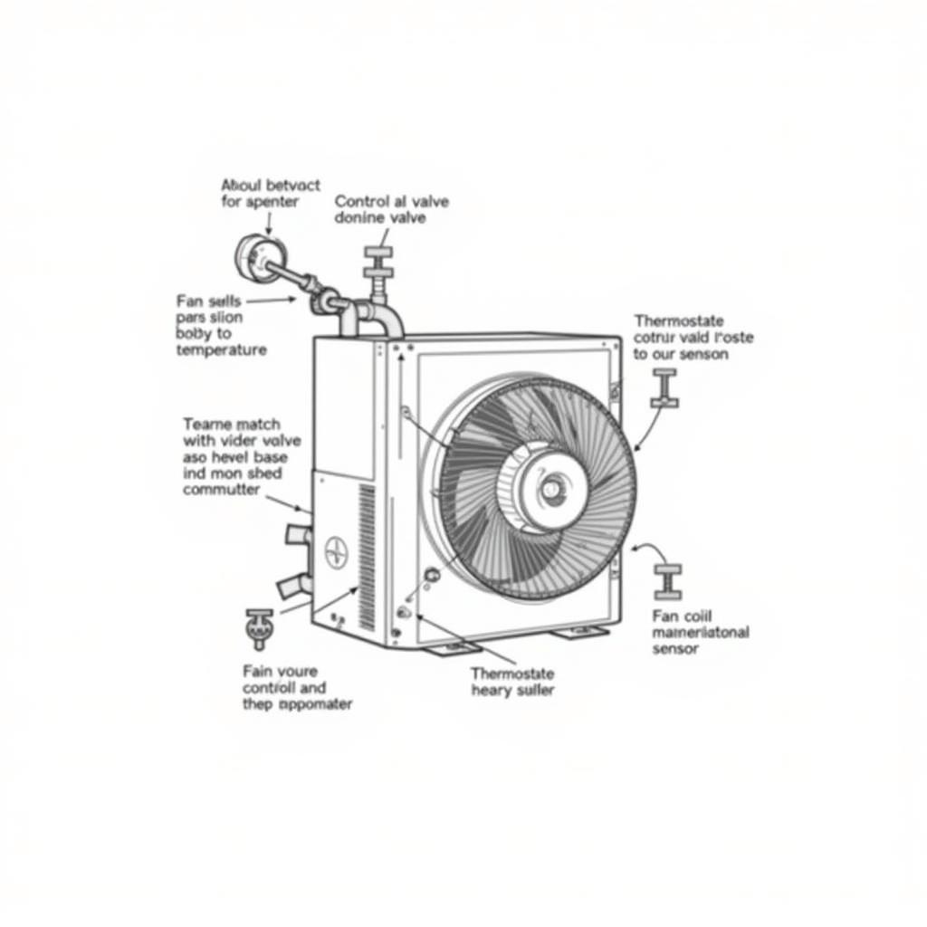
A Fan Coil Unit Analog Diagram is essential for understanding the inner workings of these crucial HVAC components. Within the first 50 words, we’ll delve into this schematic, exploring its symbols and connections, providing a comprehensive guide for both technicians and curious minds. catalogue fan coil unit analog diagram
Decoding the Fan Coil Unit Analog Diagram: A Comprehensive Guide
Fan coil units (FCUs) are the workhorses of many HVAC systems, providing localized heating and cooling. Understanding their operation, particularly through a fan coil unit analog diagram, is key for troubleshooting and maintenance. These diagrams provide a visual representation of the FCU’s components and their interconnections.
Key Components and Their Representation
A typical fan coil unit analog diagram depicts components like the fan motor, control valve, thermostat, and various sensors. These are represented by standardized symbols, creating a universal language for HVAC professionals. The diagram illustrates the electrical and water flow paths, demonstrating how the system functions.  Fan Coil Unit Analog Diagram Components
For instance, the fan motor is often represented by a circle with an “M” inside, while the control valve is typically depicted as a triangle. Understanding these symbols is crucial for interpreting the diagram effectively. They allow technicians to quickly identify components and trace the flow of energy and fluids through the system.
Interpreting the Connections and Flow
The lines connecting the symbols in a fan coil unit analog diagram represent the electrical wiring and piping. Following these lines allows you to understand the sequence of operations and how different components interact. For example, the diagram will show how the thermostat signals the control valve to regulate water flow and the fan motor to adjust airflow.
“A well-understood fan coil unit analog diagram is like a roadmap for efficient HVAC system management,” says HVAC specialist, Robert Miller, P.E. “It empowers technicians to diagnose problems quickly and accurately, minimizing downtime and maximizing comfort.”
Using the Diagram for Troubleshooting
Perhaps the most significant value of a fan coil unit diagram lies in its application for troubleshooting. By comparing the actual system behavior with the expected behavior depicted in the diagram, technicians can pinpoint the source of malfunctions. For instance, if the fan is not running, the diagram can help trace the electrical circuit to identify a potential break or faulty component.
What does a fan coil unit analog diagram look like?
A fan coil unit analog diagram typically uses standard symbols to represent various components, connected by lines indicating wiring and piping.
How can a fan coil unit analog diagram help with troubleshooting?
It allows technicians to trace the flow of electricity and water, comparing the expected behavior with the actual system performance to pinpoint malfunctions.
Leveraging the Diagram for Maintenance
Beyond troubleshooting, the fan coil unit analog diagram also aids in preventative maintenance. By understanding the system’s layout and components, technicians can identify areas prone to wear and tear, allowing for proactive maintenance and preventing potential failures. This contributes to the longevity and efficiency of the HVAC system.
“Preventative maintenance guided by a fan coil unit analog diagram can significantly reduce long-term operational costs,” advises Maria Sanchez, HVAC Systems Engineer. “It’s like having a checklist for keeping your FCU in optimal condition.”
chilled water fan coil systems benefit significantly from proper diagram interpretation.
 Fan Coil Unit Analog Diagram Troubleshooting
Conclusion
The fan coil unit analog diagram is an invaluable tool for understanding, troubleshooting, and maintaining FCUs. Its clear visual representation of components, connections, and flow paths empowers technicians and building managers to ensure optimal performance and longevity of these essential HVAC components. Mastering the interpretation of this diagram is crucial for anyone working with fan coil units.
FAQ
- What are the key components shown in a fan coil unit analog diagram?
- How are electrical connections represented in the diagram?
- How can the diagram be used to identify the source of malfunctions?
- What is the significance of the symbols used in the diagram?
- How does the diagram aid in preventative maintenance?
- What is the role of a control valve in a fan coil unit, as shown in the diagram?
- How does understanding the diagram contribute to the longevity of the FCU?
Need assistance with your fan coil unit? Contact us! Phone: 0903426737, Email: fansbongda@gmail.com. Our address: Tổ 9, Khu 6, Phường Giếng Đáy, Thành Phố Hạ Long, Giếng Đáy, Hạ Long, Quảng Ninh, Việt Nam. 24/7 support available.


