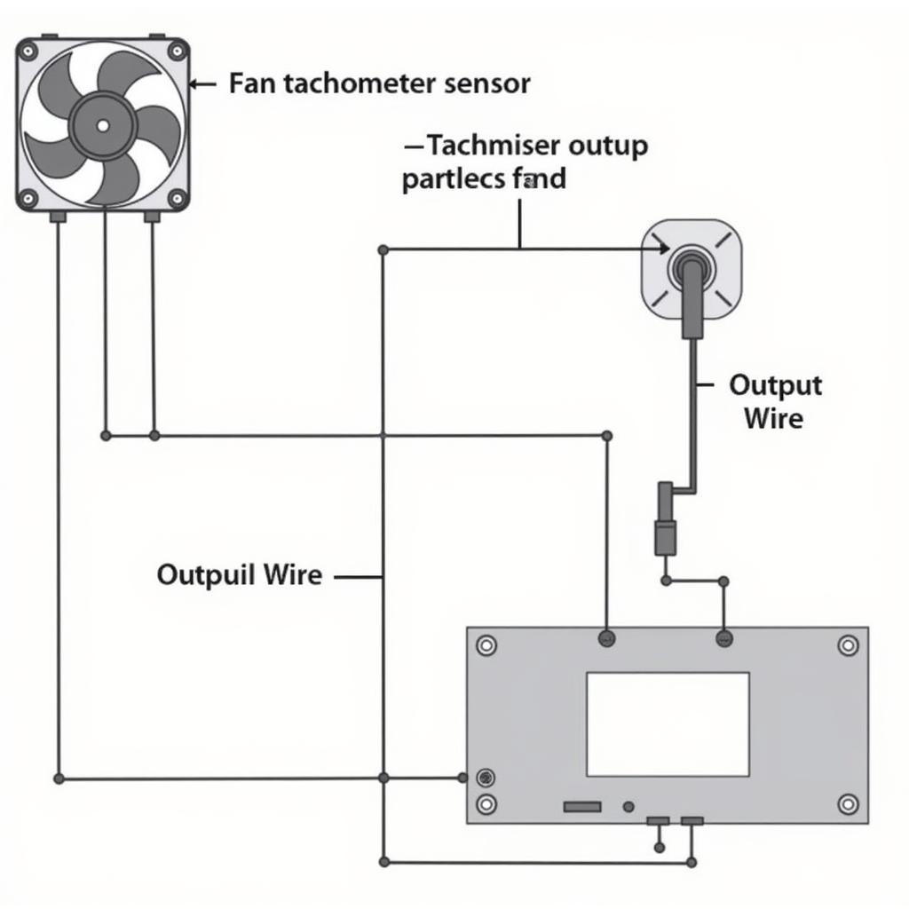
A Fan Tachometer Output Signal is crucial for monitoring and controlling cooling systems. This signal provides real-time feedback on fan speed, allowing for adjustments and optimizations to maintain optimal temperatures. This article delves into the intricacies of the fan tachometer output signal, exploring its functionality, applications, and troubleshooting.  Diagram of a Fan Tachometer Output Signal
Decoding the Fan Tachometer Output Signal
The tachometer output signal, often referred to as the “tach signal,” is a pulsed voltage generated by a sensor within the fan. This sensor, usually a Hall effect sensor, detects the rotation of the fan blades and produces a pulse for each revolution. By counting these pulses, a system can accurately determine the fan’s rotational speed, usually measured in revolutions per minute (RPM).
How the Tach Signal Works
The tach signal is typically a square wave with a frequency directly proportional to the fan speed. The voltage level of the signal can vary, but it’s commonly a TTL (Transistor-Transistor Logic) level signal, meaning it switches between a low voltage (near 0V) and a high voltage (typically 5V). This digital signal is easily interpreted by microcontrollers and other monitoring systems.
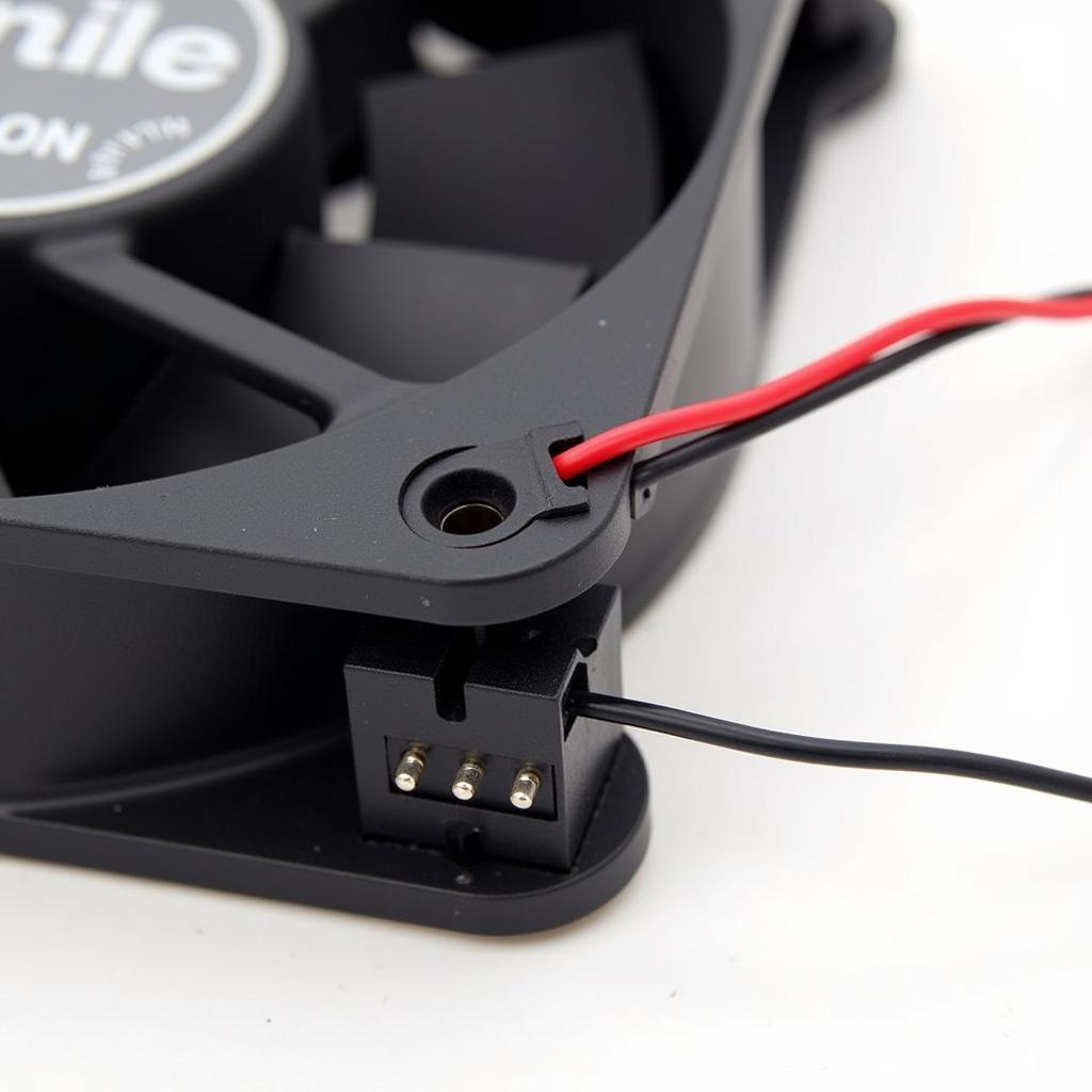
Many fans utilize a 4-wire connection. Two wires provide power to the fan motor, a third wire is the ground, and the fourth wire carries the tachometer output signal. This setup allows for both power delivery and speed monitoring. If you’re experimenting with fan control using an Arduino, understanding this 4-wire setup is essential. Check out our guide on 4 wire fan control arduino for more information.
Applications of Fan Tachometer Output Signals
The fan tachometer output signal plays a vital role in various applications, including:
- System Monitoring: The tach signal allows system monitoring software to display real-time fan speeds, enabling users to identify potential cooling issues.
- Fan Control: Based on the tach signal, systems can automatically adjust fan speeds to maintain optimal temperatures. This dynamic control minimizes noise and power consumption.
- Overheating Protection: By monitoring the tach signal, systems can detect fan failures and trigger alarms or shutdowns to prevent overheating.
- Performance Optimization: Analyzing tachometer data can help optimize cooling solutions and improve system performance.
 Computer Fan with Tachometer Connection
Troubleshooting Fan Tachometer Output Signals
Occasionally, issues can arise with the tachometer output signal. Common problems include:
- No Signal: This can be caused by a faulty fan, a damaged wire, or a malfunctioning sensor.
- Erratic Signal: A fluctuating tach signal can indicate a loose connection, a failing fan, or interference from other components.
- Incorrect Speed Reading: This can be due to a misconfigured monitoring system or a faulty sensor.
When troubleshooting, check the fan connections, inspect the wiring for damage, and test the fan with a known working system. You can also consider how different fan connection types affect performance, comparing options like 2-pin and 3-pin connections in our article fan case gắn 2 pin vs 3 pin. For fans equipped with a tachometer output, you can often find specific details on their performance characteristics. You can learn more about fans with this feature in our article on fan with tachometer output.
Why is the Fan Tachometer Output Signal Important?
The fan tachometer output signal provides critical information about fan performance. Without this signal, systems would be unable to effectively regulate cooling, potentially leading to overheating and system instability.
How Can I Connect Multiple Fans with Tachometer Outputs?
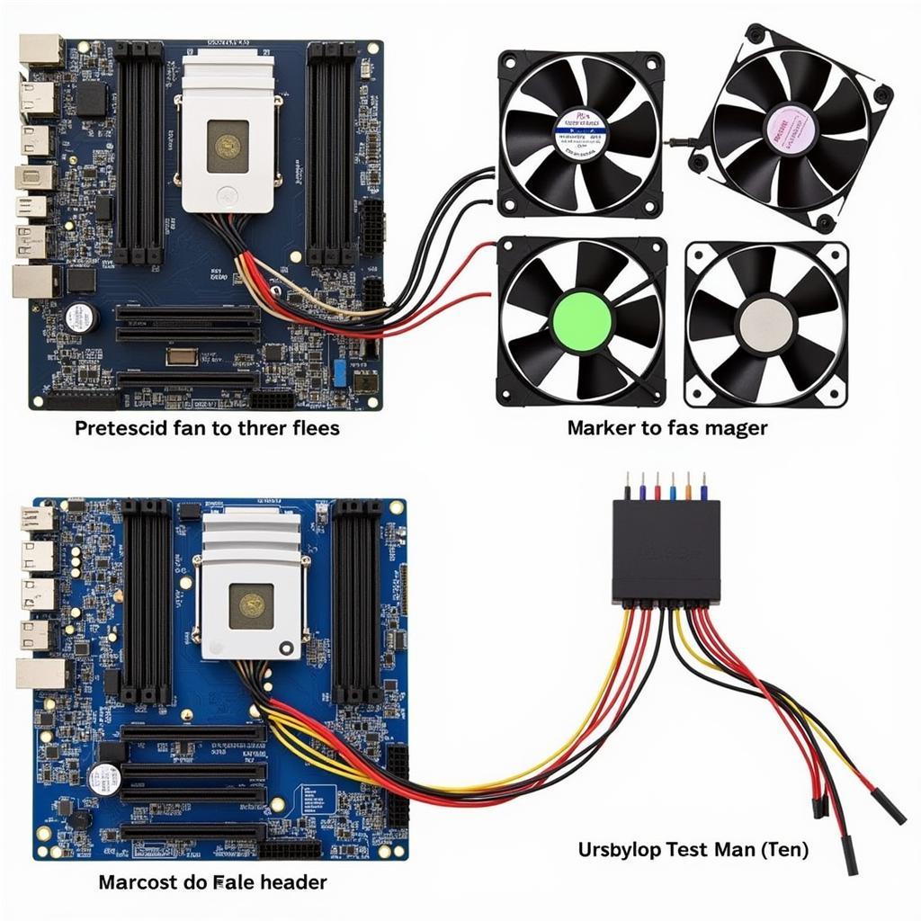
Connecting multiple fans with tachometer outputs often involves daisy-chaining or using a fan hub. For more information on connecting multiple fans, see our guide on daisy chain computer fans. Another important consideration when connecting fans is choosing the correct header on your motherboard. Our article on asus pump header or fan header can help you make the right decision.  Multiple Fans Connected to a Motherboard
Conclusion
The fan tachometer output signal is a vital component of modern cooling systems. By providing real-time feedback on fan speed, it allows for precise control, efficient cooling, and enhanced system reliability. Understanding the fan tachometer output signal is essential for anyone building or maintaining a computer system.
FAQ:
- What is a fan tachometer output signal?
- How does a tachometer sensor work?
- What are the applications of a fan tachometer output signal?
- How do I troubleshoot a fan tachometer output signal?
- What are the different types of fan connectors?
- How do I connect multiple fans to a single header?
- What is the difference between a 2-pin and a 4-pin fan connector?
Need support? Contact us 24/7 at Phone: 0903426737, Email: fansbongda@gmail.com or visit our address: Lot 9, Area 6, Gieng Day Ward, Ha Long City, Gieng Day, Ha Long, Quang Ninh, Vietnam.


