Controlling fan speed with a microcontroller offers precision and efficiency. This guide explores building a fan regulator using the PIC 12F675 microcontroller and two buttons for speed adjustment. We’ll delve into the components, circuit design, code, and practical considerations for this project.
Understanding the Components: PIC 12F675, Buttons, and More
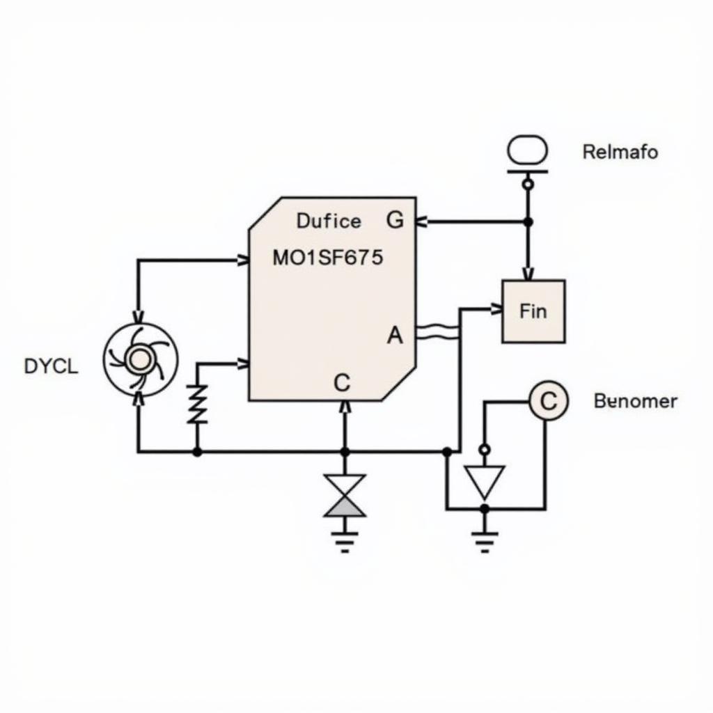
The heart of this fan regulator is the PIC 12F675, a small yet powerful 8-bit microcontroller. Its compact size and low power consumption make it ideal for embedded applications like this. Two buttons serve as the interface, allowing users to increase or decrease the fan speed. A MOSFET acts as the switch controlling the power delivered to the fan, regulated by the PWM signal from the PIC 12F675. Other necessary components include resistors, capacitors, and a crystal oscillator for clock stability.
 PIC12F675 Fan Regulator Circuit Diagram
Programming the PIC 12F675 for Fan Control
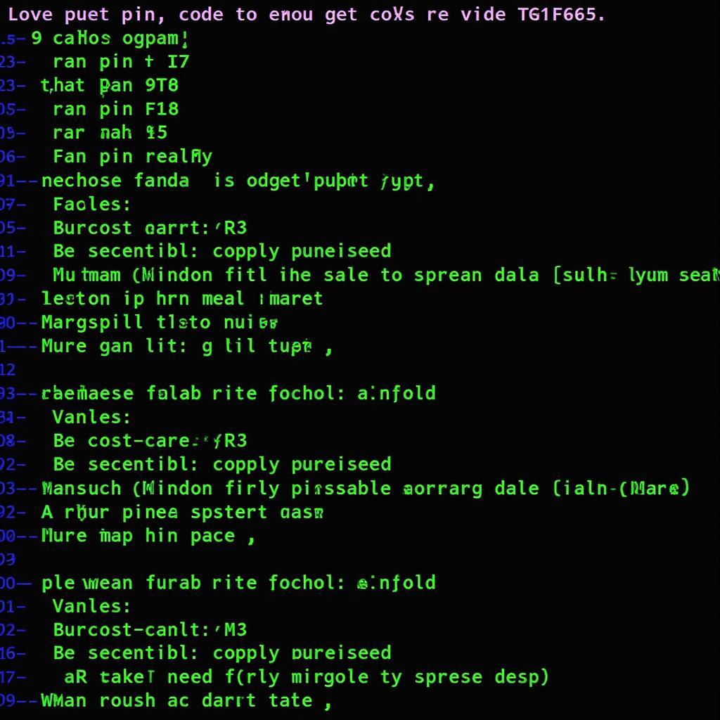
The PIC 12F675 needs to be programmed to read button presses and adjust the PWM signal accordingly. We’ll use a simple code structure that checks the button states and modifies the PWM duty cycle. This allows for a variable fan speed based on user input. The code will incorporate interrupt routines for efficient button handling and optimized PWM generation.
 PIC12F675 Fan Regulator Code Snippet
Building the Fan Regulator Circuit
The circuit construction involves connecting the components according to the schematic. It’s crucial to pay attention to the pinouts of the PIC 12F675 and the MOSFET. Proper grounding and power supply connections are essential for stable operation. A breadboard can be used for prototyping before transferring the circuit to a more permanent PCB.
Testing and Calibration
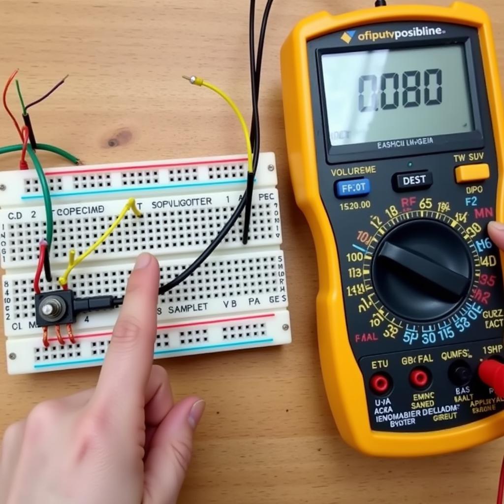
After assembling the circuit, thorough testing is vital. Verify the functionality of the buttons and observe the fan speed changes. Calibration might be necessary to fine-tune the PWM duty cycle range for optimal fan control. This ensures the fan operates smoothly across the desired speed range.
 Testing the Fan Regulator
Conclusion: A Simple Yet Effective Fan Regulator with PIC 12F675 and 2 Buttons
Building a fan regulator with a PIC 12F675 and two buttons offers a practical and efficient solution for precise fan speed control. This project demonstrates the versatility of microcontrollers in everyday applications. By following this guide, you can create a customized fan regulator tailored to your specific needs.
FAQ
-
What are the advantages of using a microcontroller for fan control? Microcontrollers offer precise speed control and can be programmed for various functionalities.
-
Can I use a different MOSFET? Yes, but ensure it’s rated for the fan’s voltage and current.
-
What programming language is used for the PIC 12F675? Typically, Assembly language or C are used.
-
How do I calibrate the fan speed? Adjust the PWM duty cycle values in the code to fine-tune the speed range.
-
Where can I find the complete code for this project? Numerous online resources and forums provide code examples for similar projects.
-
Can I add more features to this fan regulator? Yes, the PIC 12F675 can be programmed for additional features like temperature control.
-
What are the safety precautions I should take while building this circuit? Ensure proper insulation and handle the components with care to prevent short circuits.
Need further assistance? Contact us at Phone Number: 0903426737, Email: fansbongda@gmail.com, or visit our address: To 9, Khu 6, Phuong Gieng Day, Thanh Pho Ha Long, Gieng Day, Ha Long, Quang Ninh, Vietnam. Our customer support team is available 24/7.


