When interfacing CMOS (Complementary Metal-Oxide-Semiconductor) and TTL (Transistor-Transistor Logic) devices, the concept of “Fan Out Number Of Ics From Cmos To Ttl” is crucial for ensuring reliable operation. This refers to the number of TTL inputs a single CMOS output can drive without compromising signal integrity. Understanding this concept ensures proper circuit design and prevents unexpected behavior.
Decoding Fan Out: CMOS Driving TTL
The fan out number represents the driving capability of a CMOS output. A higher fan out indicates that a CMOS output can drive more TTL inputs simultaneously. This capability depends on the output current of the CMOS device and the input current requirements of the TTL device.
Factors Affecting Fan Out
Several factors influence the fan out number when interfacing CMOS with TTL. These include:
- CMOS Output Current: A CMOS output with a higher current capacity can drive more TTL inputs.
- TTL Input Current: TTL inputs with lower current requirements place less burden on the CMOS output, allowing for a higher fan out.
- Voltage Levels: CMOS and TTL operate at slightly different voltage levels. Careful consideration of these differences is essential to ensure reliable signal transmission.
- Temperature: Temperature variations can affect the operating characteristics of both CMOS and TTL devices, impacting the fan out capability.
Calculating Fan Out
Calculating the fan out number involves comparing the CMOS output current with the total input current of the TTL devices it drives. For example, if a CMOS output can source 10mA and each TTL input requires 0.5mA, the fan out number would be 20 (10mA / 0.5mA).
Practical Considerations
While the calculated fan out number provides a theoretical limit, practical considerations often necessitate using a lower number. This ensures a safety margin and accounts for variations in device characteristics.
- Noise Margin: Using a lower fan out improves noise immunity.
- Signal Degradation: Driving too many TTL inputs can lead to signal degradation, causing unreliable operation.
- Temperature Effects: Consider derating the fan out number at higher temperatures to account for changes in device performance.
 Fan Out Calculation Example
Best Practices for Interfacing CMOS to TTL
Several best practices can ensure reliable operation when interfacing CMOS and TTL:
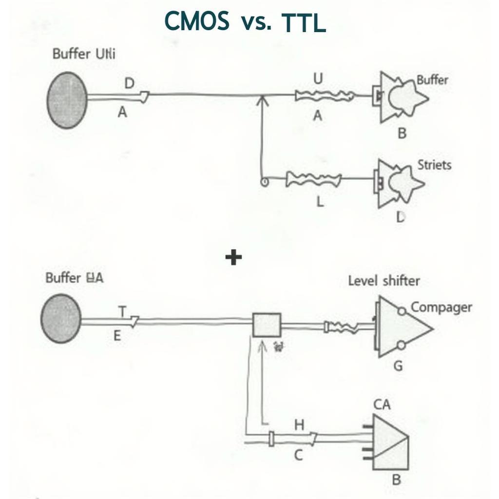
- Buffer ICs: Use buffer ICs to increase the fan out capability when driving a large number of TTL inputs.
- Level Shifters: Employ level shifters to ensure proper voltage translation between CMOS and TTL.
- Pull-up Resistors: Consider using pull-up resistors on TTL inputs to prevent floating inputs and improve noise immunity.
Common Pitfalls to Avoid
- Exceeding Fan Out Limits: Avoid exceeding the fan out limit of the CMOS device. This can lead to unreliable operation and damage the devices.
- Ignoring Voltage Levels: Ensure proper voltage compatibility between CMOS and TTL devices.
- Neglecting Temperature Effects: Consider the impact of temperature variations on device performance.
 CMOS-TTL Interfacing Best Practices
Conclusion
Understanding the “fan out number of ics from cmos to ttl” is essential for successful interfacing between these two logic families. By carefully considering the factors affecting fan out and following best practices, designers can ensure reliable and robust circuit operation.
FAQs
- What is fan out in digital logic?
- How does temperature affect fan out?
- Why is it important to stay within the fan out limit?
- What are the common problems when interfacing CMOS and TTL?
- How can buffer ICs improve fan out capability?
- What are level shifters and why are they used?
- How do pull-up resistors improve noise immunity in TTL circuits?
Common Scenarios
- Scenario 1: Driving multiple TTL LEDs from a single CMOS output.
- Scenario 2: Interfacing a CMOS sensor with a TTL-based microcontroller.
- Scenario 3: Connecting a CMOS logic gate to multiple TTL inputs.
Related Questions and Articles
- What are the differences between CMOS and TTL logic families?
- How to choose the right logic family for your application?
- Understanding voltage levels and current requirements in digital circuits.
Need help? Contact us at Phone: 0903426737, Email: fansbongda@gmail.com or visit us at Address: To 9, Khu 6, Phuong Gieng Day, Thanh Pho Ha Long, Gieng Day, Ha Long, Quang Ninh, Vietnam. We have a 24/7 customer support team.


