A brushless DC fan, often shortened to BLDC fan, stands as a testament to efficient cooling technology. But have you ever wondered about the intricate workings hidden within its unassuming frame? The answer lies in understanding the circuit schematic of a BLDC fan. This seemingly complex diagram is your roadmap to uncovering the secrets behind this marvel of engineering.
Deciphering the Core Components
At the heart of the BLDC fan circuit schematic lies a carefully orchestrated arrangement of electronic components, each playing a crucial role:
-
Microcontroller: The brain of the operation, this integrated circuit manages all aspects of the fan’s operation. It receives signals from the Hall sensors, processes them, and sends precise instructions to the MOSFET drivers.
-
MOSFET Drivers: Acting as intermediaries between the microcontroller and the motor, these components amplify the signals from the microcontroller, providing the necessary power to drive the motor windings.
-
Hall Sensors: These magnetic sensors are strategically positioned within the motor housing. They detect the rotor’s position and relay this information back to the microcontroller, enabling precise control over the commutation sequence.
-
Motor Windings: Wrapped around the stator, these coils are energized in a specific sequence to generate the rotating magnetic field that propels the rotor.
The Dance of Electrons: How It Works
The beauty of a BLDC fan lies in its elegant operation. As power courses through the circuit, the microcontroller, guided by the input from the Hall sensors, orchestrates a symphony of controlled electromagnetic interactions.
-
Rotor Position Detection: The Hall sensors detect the rotor’s magnetic field and send corresponding signals to the microcontroller.
-
Commutation Sequence: The microcontroller processes the sensor data and determines the appropriate sequence for energizing the motor windings.
-
Winding Energization: The MOSFET drivers, under the microcontroller’s command, energize specific motor windings, creating a rotating magnetic field.
-
Rotor Alignment: The rotor, with its permanent magnets, aligns itself with the rotating magnetic field, causing it to spin.
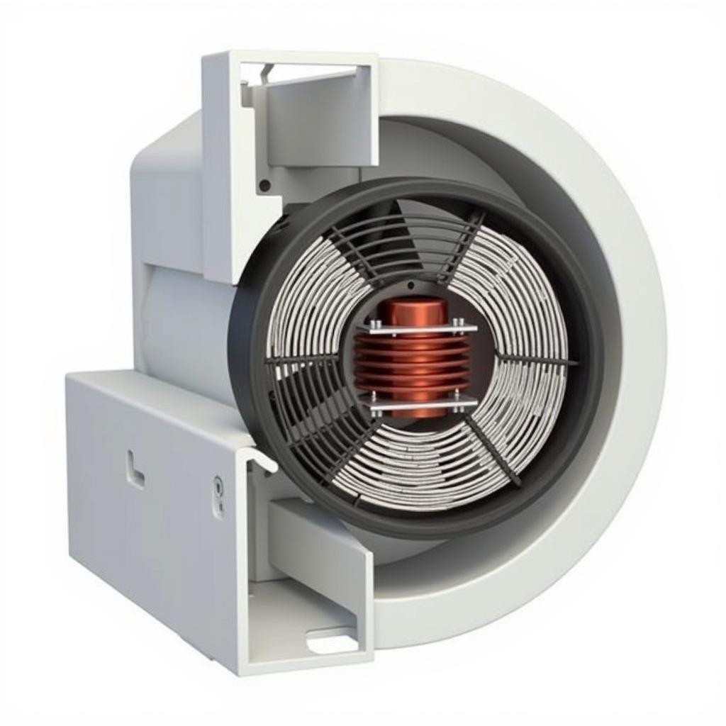 BLDC Fan Rotor and Stator Configuration
Advantages of the BLDC Fan Design
The BLDC fan’s unique design offers several advantages over traditional brushed DC fans:
-
Enhanced Efficiency: The absence of brushes eliminates friction, leading to reduced energy loss and increased efficiency. This translates to lower power consumption and longer battery life in portable devices.
-
Increased Lifespan: Without brushes to wear down, BLDC fans boast a significantly longer lifespan, reducing maintenance and replacement costs.
-
Reduced Noise: The electronic commutation process eliminates the noise associated with brushes, making BLDC fans significantly quieter.
-
Precise Speed Control: The microcontroller allows for precise speed control, enabling the fan to operate at optimal speeds for varying cooling demands.
Troubleshooting Common Issues
While BLDC fans are generally reliable, occasional issues can arise. Understanding the circuit schematic can be invaluable in diagnosing and resolving these problems. Here are a few common issues and their potential causes:
-
Fan Not Spinning: This could be due to a faulty microcontroller, damaged MOSFET drivers, or a disconnected power supply.
-
Erratic Fan Speed: Fluctuating Hall sensor signals, a malfunctioning microcontroller, or loose connections can lead to inconsistent fan speeds.
-
Overheating: Insufficient heat sink size, inadequate ventilation, or a short circuit in the motor windings can result in overheating.
Conclusion
The circuit schematic of a BLDC fan is a testament to the ingenuity of modern electronics. By understanding the roles of its components and the principles governing its operation, we gain a deeper appreciation for the technology that keeps our devices cool and running smoothly. Whether you’re a tech enthusiast, a DIYer, or simply curious about the inner workings of everyday gadgets, delving into the world of BLDC fan circuitry offers a fascinating journey into the realm of electronics.
FAQs
1. What is the purpose of the Hall sensors in a BLDC fan?
Hall sensors detect the rotor’s position and relay this information to the microcontroller, ensuring proper commutation sequencing.
2. Why are BLDC fans more efficient than brushed DC fans?
The absence of brushes eliminates friction, reducing energy loss and increasing efficiency.
3. Can I adjust the speed of a BLDC fan?
Yes, the microcontroller in a BLDC fan allows for precise speed control.
4. What are some common signs of a faulty BLDC fan?
Common signs include the fan not spinning, erratic fan speed, or overheating.
5. Where can I find more information about BLDC fan circuitry?
Numerous online resources, forums, and manufacturer websites provide detailed information on BLDC fan technology.
For further assistance, please contact us at Phone Number: 0903426737, Email: [email protected] or visit us at Address: Group 9, Area 6, Gieng Day Ward, Ha Long City, Gieng Day, Ha Long, Quang Ninh, Vietnam. Our customer service team is available 24/7 to assist you.