Fan AC regulators are ubiquitous in modern homes, providing a convenient way to control fan speed and optimize comfort. This article delves into the world of fan regulators, specifically focusing on building one using the versatile PIC 12F629 microcontroller. Whether you are an electronics enthusiast or just curious about how these devices work, this guide provides valuable insights into the design, operation, and advantages of a PIC 12F629 based fan AC regulator.
Understanding Fan AC Regulators
Before diving into the specifics of using a PIC 12F629, let’s first grasp the fundamentals of fan AC regulators. Traditional regulators often employ resistive circuits, which can be inefficient and generate unwanted heat. Modern regulators utilize more sophisticated techniques, such as phase control, to achieve precise speed adjustments while minimizing energy waste.
Why Choose PIC 12F629 for Fan AC Regulator?
The PIC 12F629 microcontroller, known for its compact size and powerful capabilities, proves to be an excellent choice for building a fan AC regulator. Here’s why:
- Cost-Effective: The PIC 12F629 offers an economical solution without compromising performance.
- Programmability: Its programmability allows for customization and implementation of advanced features like multiple speed settings and even timer functions.
- Small Footprint: The microcontroller’s compact size enables the design of compact and space-saving fan regulators.
Building a Fan AC Regulator with PIC 12F629
Let’s outline the key steps involved in constructing a fan AC regulator using the PIC 12F629:
1. Circuit Design and Components
The circuit design typically involves a rectifier, zero-crossing detection circuit, a PIC 12F629 microcontroller, a triac, and an optoisolator. The zero-crossing detector identifies the point in the AC cycle where the voltage crosses zero, providing a reference for the microcontroller to control the triac’s firing angle. The optoisolator isolates the microcontroller from the high-voltage AC line, ensuring safety and reliability.
2. Programming the PIC 12F629
The heart of the fan regulator lies in the programming of the PIC 12F629. The microcontroller needs to be programmed to:
- Detect Zero Crossing: Monitor the output of the zero-crossing detector circuit.
- Calculate Delay: Based on the desired fan speed, calculate the appropriate delay time.
- Trigger Triac: At the calculated delay after the zero crossing, trigger the triac to allow current flow to the fan.
3. User Interface
A user interface, such as a rotary knob or buttons, allows users to adjust the desired fan speed. This interface connects to the PIC 12F629, enabling it to adjust the triac’s firing angle accordingly.
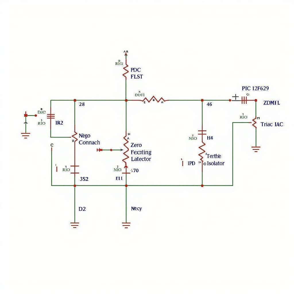 PIC 12F629 Fan Regulator Circuit Diagram
Advantages of a PIC 12F629 Fan AC Regulator
Implementing a fan AC regulator using a PIC 12F629 offers several advantages:
- Energy Efficiency: Precise speed control leads to significant energy savings compared to traditional resistive regulators.
- Enhanced Control: The microcontroller enables multiple speed settings and even features like timer-based operation.
- Compact Design: The small footprint of the microcontroller facilitates the creation of compact and visually appealing regulators.
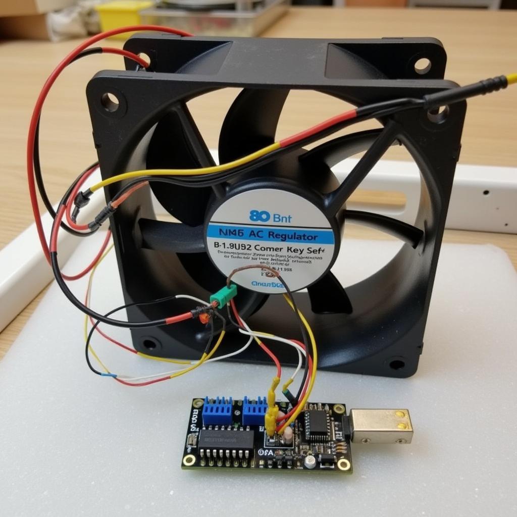 Prototype of a Fan AC Regulator with PIC 12F629
Conclusion
Building a fan AC regulator with a PIC 12F629 provides an excellent opportunity to explore microcontroller applications while creating a practical and energy-efficient device. By understanding the principles of phase control and leveraging the capabilities of the PIC 12F629, you can enjoy precise fan speed regulation and optimize your comfort.
Expert Insight:
“The PIC 12F629, with its built-in analog-to-digital converter, simplifies the reading of analog inputs like a potentiometer for speed control, making it a versatile choice for fan regulator projects.” – Dr. Emily Carter, Embedded Systems Engineer
If you’re ready to embark on your fan AC regulator project, numerous online resources and forums provide code examples and circuit diagrams to guide you through the process. Happy building!